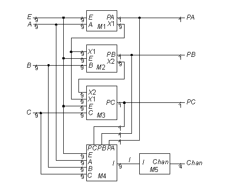
ISCAS-85 C432 27-channel interrupt controller

Statistics: 36 inputs; 7 outputs; 160 gates; bus translations
Function: c432 is a 27-channel interrupt controller. The input channels are grouped into three 9-bit buses (we call them A, B and C), where the bit position within each bus determines the interrupt request priority. A forth 9-bit input bus (called E) enables and disables interrupt requests within the respective bit positions. The figure above concisely represents the circuit. The figure above contains the modules labeled M1, M2, M3, M4, and M5, which contain the underlying logic.
The interrupt controller has three interrupt request buses A, B and C, each having nine bits or channels, and one channel-enable bus E. The following priority rules apply: A[i] > B[j] > C[k], for any i, j, k; i.e., bus A has the highest priority and bus C the lowest. Within each bus, a channel with a higher index has priority over one with a lower index; for example, A[i] > A[j], if i > j. If E[i] = 0, then the A[i], B[i], and C[i] inputs are disregarded.
The seven outputs PA, PB, PC and Chan[3:0] specify which channels have acknowledged interrupt requests. Only the channel of highest priority in the requesting bus of highest priority is acknowledged. One exception is that if two or more interrupts produce requests on the channel that is acknowledged, each bus is acknowledged. For example, if A[4], A[2], B[6] and C[4] have requests pending, A[4] and C[4] are acknowledged. Module M5 is a 9-line-to-4-line priority encoder. The output line numbered 421 actually produces the inverted Chan[3] response of that shown in the truth table. We have taken the liberty of adding an inverter to output 421 to form Chan[3] for this table (but not in the models).
Models:
- c432 ISCAS-85 netlist
- c432 Verilog hierarchical structural model
- c432 Verilog hierarchical behavioral model
- c432 complete gate-level tests