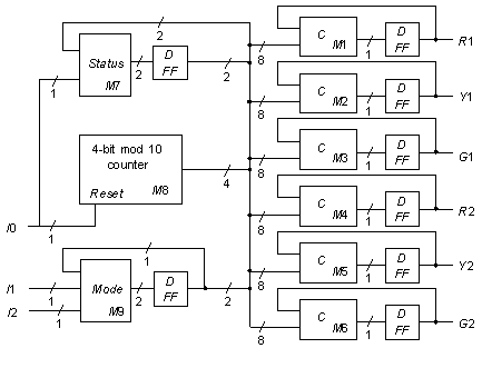
ISCAS-89 s298 Traffic Light Controller

Statistics: 3 inputs; 6 outputs; 133 gates;
Function: The high-level model of the s298 traffic light controller is shown above. After being reset by activating input I0, the controller has a repeating green-yellow-red light sequence that is 20 clock cycles in length. For the main direction of travel, the sequence is: 14 green, two yellow, and four red; for the opposing direction: 16 red, two green and two yellow. When the I1 input is pulsed, the controller changes to a repeating light pattern that is twice as fast, that is 10 clock cycles in length. If the I2 input is pulsed, the controller enters a blinking red/blinking yellow mode. M1-M6 are simple "random" combinational logic blocks that generate the six light values; M7 is a status logic block; M8 is a modulo-10 counter; and M9 controls the two mode lines.
Models:
- s298 ISCAS-89 netlist
- s298 Verilog hierarchical structural model
- s298 Verilog hierarchical behavioral model
- s298 complete gate-level tests